
With the Concrete Design add-on, you can perform the fatigue design of members and surfaces according to EN 1992‑1‑1, Chapter 6.8.
For the fatigue design, you can optionally select two methods or design levels in the design configurations:
- Design Level 1: Simplified design according to 6.8.6 and 6.8.7(2): The simplified design is performed for frequent action combinations according to EN 1992‑1‑1, Chapter 6.8.6 (2), and EN 1990, Eq. (6.15b) with the traffic loads relevant in the serviceability state. A maximum stress range according to 6.8.6 is designed for the reinforcing steel. The concrete compressive stress is determined by means of the upper and lower allowable stress according to 6.8.7(2).
- Design Level 2: Design of damage equivalent stress acc. to 6.8.5 and 6.8.7(1) (simplified fatigue design): The design using damage equivalent stress ranges is performed for the fatigue combination according to EN 1992‑1‑1, Chapter 6.8.3, Eq. (6.69) with the specifically defined cyclic action Qfat.

In the "Shear Reinforcement" tab, you can select the option "Cross-ties over free rebars with active selection in graphic". It allows you to arrange additional cross-ties on free rebars of the longitudinal reinforcement.
You can activate or deactivate the position of the cross-ties in the Info Graphic. The cross-ties are applied for the ultimate limit state design and the structural design checks. They are available for the design according to EN 1992‑1‑1.
Go to Explanatory Video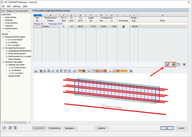
- Full integration in RFEM/RSTAB with import of geometry and load case data
- Automatic selection of members for design according to specified criteria (e.g. only vertical members)
- In connection with the extension EC2 for RFEM/RSTAB, you can perform the design of reinforced concrete compression elements according to the method based on nominal curvature in compliance with EN 1992 -1‑1:2004 (Eurocode 2) and the following National Annexes:
-
 DIN EN 1992-1-1/NA/A1:2015-12 (Germany)
 -
 ÖNORM B 1992-1-1:2018-01 (Austria)
 -
 Belgium NBN EN 1992-1-1 ANB:2010 for design at normal temperature, and NBN EN 1992-1-2 ANB:2010 for fire resistance design (Belgium)
 -
 BDS EN 1992-1-1:2005/NA:2011 (Bulgaria)
 -
 EN 1992-1-1 DK NA:2013 (Denmark)
 -
 NF EN 1992-1-1/NA:2016-03 (France)
 -
 SFS EN 1992-1-1/NA:2007-10 (Finland)
 -
 UNI EN 1992-1-1/NA:2007-07 (Italy)
 -
 LVS EN 1992-1-1:2005/NA:2014 (Latvia)
 -
 LST EN 1992-1-1:2005/NA:2011 (Lithuania)
 -
 MS EN 1992-1-1:2010 (Malaysia)
 -
 NEN-EN 1992-1-1+C2:2011/NB:2016 (Netherlands)
 -
 NS EN 1992-1 -1:2004-NA:2008 (Norway)
 -
 PN EN 1992-1-1/NA:2010 (Poland)
 -
 NP EN 1992-1-1/NA:2010-02 (Portugal)
 -
 SR EN 1992-1-1:2004/NA:2008 (Romania)
 -
 SS EN 1992-1-1/NA:2008 (Sweden)
 -
 SS EN 1992-1-1/NA:2008-06 (Singapore)
 -
 STN EN 1992-1-1/NA:2008-06 (Slovakia)
 -
 SIST EN 1992-1-1:2005/A101:2006 (Slovenia)
 -
 UNE EN 1992-1-1/NA:2013 (Spain)
 -
 CSN EN 1992-1-1/NA:2016-05 (Czech Republic)
 -
 BS EN 1992-1-1:2004/NA:2005 (United Kingdom)
 -
 TKP EN 1992-1-1:2009 (Belarus)
 -
 CYS EN 1992-1-1:2004/NA:2009 (Cyprus)
-
- In addition to the National Annexes (NA) listed above, you can define a specific NA, applying user-defined limit values and parameters.
- Optional consideration of creep
- Diagram-based determination of buckling lengths and slenderness from the restraint ratios of columns
- Automatic determination of ordinary and unintentional eccentricity from additionally available eccentricity according to the second-order analysis
- Design of monolithic structures and precast elements
- Analysis with regard to the standard reinforced concrete design
- Determination of internal forces according to the linear static analysis and the second-order analysis
- Analysis of governing design locations along the column due to existing loading
- Output of required longitudinal and stirrup reinforcement
- Fire resistance design according to the simplified method (zone method) according to EN 1992-1-2 allowing the fire resistance design of brackets.
- Fire resistance design with optional longitudinal reinforcement design according to DIN 4102-22:2004 or DIN 4102-4:2004, Table 31
- Longitudinal and link reinforcement proposal with graphic display in 3D rendering
- Summary of design ratios, including all design details
- Graphical representation of relevant design details in RFEM/RSTAB work window

- Import of relevant information and results from RFEM
- Integrated, editable material and section library
- The module extension EC2 for RFEM enables the design of reinforced concrete members according to EN 1992‑1‑1:2004 (Eurocode 2) and the following National Annexes:
-
DIN EN 1992-1-1/NA/A1:2015-12 (Germany)
-
ÖNORM B 1992-1-1:2018-01 (Austria)
-
NBN EN 1992-1-1 ANB:2010 (Belgium)
-
BDS EN 1992-1-1:2005/NA:2011 (Bulgaria)
-
EN 1992-1-1 DK NA:2013 (Denmark)
-
NF EN 1992-1-1/NA:2016-03 (France)
-
SFS EN 1992-1-1/NA:2007-10 (Finland)
-
UNI EN 1992-1-1/NA:2007-07 (Italy)
-
LVS EN 1992-1-1:2005/NA:2014 (Latvia)
-
LST EN 1992-1-1:2005/NA:2011 (Lithuania)
-
MS EN 1992-1-1:2010 (Malaysia)
-
NEN-EN 1992-1-1+C2:2011/NB:2016 (Netherlands)
- NS EN 1992-1 -1:2004-NA:2008 (Norway)
-
PN EN 1992-1-1/NA:2010 (Poland)
-
NP EN 1992-1-1/NA:2010-02 (Portugal)
-
SR EN 1992-1-1:2004/NA:2008 (Romania)
-
SS EN 1992-1-1/NA:2008 (Sweden)
-
SS EN 1992-1-1/NA:2008-06 (Singapore)
-
STN EN 1992-1-1/NA:2008-06 (Slovakia)
-
SIST EN 1992-1-1:2005/A101:2006 (Slovenia)
-
UNE EN 1992-1-1/NA:2013 (Spain)
-
CSN EN 1992-1-1/NA:2016-05 (Czech Republic)
-
BS EN 1992-1-1:2004/NA:2005 (United Kingdom)
-
TKP EN 1992-1-1:2009 (Belarus)
-
CYS EN 1992-1-1:2004/NA:2009 (Cyprus)
-
In addition to the National Annexes (NA) listed above, you can define a specific NA, applying user‑defined limit values and parameters.
- Sensible and complete presetting of input parameters
- Punching design on columns, wall ends, and wall corners
- Optional arrangement of an enlarged column head
- Automatic recognition of the position of the punching node from the RFEM model
- Detection of curves or splines as boundary of the control perimeter
- Automatic consideration of all slab openings defined in the RFEM model
- Structure and graphical display of the control perimeter before calculation starts
- Qualitative determination of punching shear reinforcement
- Optional design with unsmoothed shear stress along the control perimeter that corresponds to the actual shear stress distribution in the FE model
- Determination of the load increment factor β via full-plastic shear distribution as constant factors according to EN 1992‑1‑1, Sect. 6.4.3 (3), based on EN 1992‑1‑1, Fig. 6.21N or by user‑defined specification
- Integration of design software by Halfen, a producer of shear rails
- Numerical and graphical display of results (3D, 2D, and in sections)
- Punching shear design with or without punching shear reinforcement
- Optional consideration of minimum moments according to EN 1992‑1‑1 when determining longitudinal reinforcement
- Design or analysis of longitudinal reinforcement
- Complete integration of results in the RFEM printout report
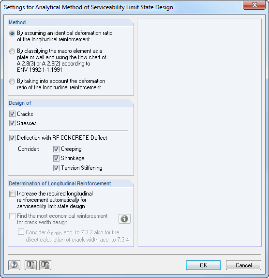
The deformation analysis according to the approximation method defined in standards (for example, deformation analysis according to EN 1992‑1‑1, 7.4.3) applies to the calculation of "effective stiffnesses" in the finite elements in accordance with the existing limit state of the concrete with or without cracks. These stiffnesses are used to determine the surface deformation by repeated FEM calculation.
The effective stiffness calculation of finite elements takes into account a reinforced concrete cross-section. Based on the internal forces determined for the serviceability limit state in RFEM, the program classifies the reinforced concrete cross-section as 'cracked' or 'uncracked'. If the tension stiffening at a section should be considered as well, a distribution coefficient (according to EN 1992-1-1, Eq. 7.19, for example) is used. The material behavior for the concrete is assumed to be linear-elastic in the compression and tension zone until the concrete tensile strength is reached. This is reached exactly in the serviceability limit state.
When determining the effective stiffnesses, creep and shrinkage are taken into account at the "cross-section level". The influence of shrinkage and creep in statically indeterminate systems is not taken into account in this approximation method (for example, tensile forces from shrinkage strain in systems restrained on all sides are not determined and must be considered separately). In summary, RF-CONCRETE Deflect calculates deformations in two steps:
- Calculation of effective stiffnesses of the reinforced concrete cross-section assuming linear-elastic conditions
- Calculation of the deformation using the effective stiffnesses with FEM
In addition to the reinforced concrete design according to the international standard EN 1992‑1‑1:2004 + A1:2014, the module extension provides the National Annexes for the modules mentioned above. Currently, the following NAs are available:
-
DIN EN 1992-1-1/NA/A1:2015-12 (Germany)
-
ÖNORM B 1992-1-1:2011-12 (Austria)
-
Belgium NBN EN 1992-1-1 ANB:2010 for design at normal temperature, and NBN EN 1992-1-2 ANB:2010 for fire resistance design (Belgium)
-
BDS EN 1992-1-1:2005/NA:2011 (Bulgaria)
-
EN 1992-1-1 DK NA:2013 (Denmark)
-
NF EN 1992-1-1/NA:2016-03 (France)
-
SFS EN 1992-1-1/NA:2007-10 (Finland)
-
UNI EN 1992-1-1/NA:2007-07 (Italy)
-
LVS EN 1992-1-1:2005/NA:2014 (Latvia)
-
LST EN 1992-1-1:2005/NA:2011 (Lithuania)
-
MS EN 1992-1-1:2010 (Malaysia)
-
NEN-EN 1992-1-1+C2:2011/NB:2016 (Netherlands)
-
NS EN 1992-1 -1:2004-NA:2008 (Norway)
-
PN EN 1992-1-1/NA:2010 (Poland)
-
NP EN 1992-1-1/NA:2010-02 (Portugal)
-
SR EN 1992-1-1:2004/NA:2008 (Romania)
- #flagSWE@# SS EN 1992-1-1/NA:2008 (Sweden)
-
SS EN 1992-1-1/NA:2008-06 (Singapore)
-
STN EN 1992-1-1/NA:2008-06 (Slovakia)
-
SIST EN 1992-1-1:2005/A101:2006 (Slovenia)
-
UNE EN 1992-1-1/NA:2013 (Spain)
-
CSN EN 1992-1-1/NA:2016-05 (Czech Republic)
-
BS EN 1992-1-1:2004/NA:2005 (United Kingdom)
-
TKP EN 1992-1-1:2009 (Belarus)
-
CYS EN 1992-1-1:2004/NA:2009 (Cyprus)
In addition to the National Annexes (NA) listed above, you can also define a specific NA, applying user‑defined limit values and parameters.
- Automatic import of internal forces from RFEM
- Ultimate limit state and serviceability limit state design
- The module extension EC2 for RFEM enables the design of reinforced concrete members according to EN 1992‑1‑1:2004 (Eurocode 2) and the following National Annexes:
-
DIN EN 1992-1-1/NA/A1:2015-12 (Germany)
-
ÖNORM B 1992-1-1:2018-01 (Austria)
-
NBN EN 1992-1-1 ANB:2010 (Belgium)
-
BDS EN 1992-1-1:2005/NA:2011 (Bulgaria)
-
EN 1992-1-1 DK NA:2013 (Denmark)
-
NF EN 1992-1-1/NA:2016-03 (France)
-
SFS EN 1992-1-1/NA:2007-10 (Finland)
-
UNI EN 1992-1-1/NA:2007-07 (Italy)
-
LVS EN 1992-1-1:2005/NA:2014 (Latvia)
-
LST EN 1992-1-1:2005/NA:2011 (Lithuania)
-
MS EN 1992-1-1:2010 (Malaysia)
-
NEN-EN 1992-1-1+C2:2011/NB:2016 (Netherlands)
-
NS EN 1992-1 -1:2004-NA:2008 (Norway)
-
PN EN 1992-1-1/NA:2010 (Poland)
-
NP EN 1992-1-1/NA:2010-02 (Portugal)
-
SR EN 1992-1-1:2004/NA:2008 (Romania)
-
SS EN 1992-1-1/NA:2008 (Sweden)
-
SS EN 1992-1-1/NA:2008-06 (Singapore)
-
STN EN 1992-1-1/NA:2008-06 (Slovakia)
-
SIST EN 1992-1-1:2005/A101:2006 (Slovenia)
-
UNE EN 1992-1-1/NA:2013 (Spain)
-
CSN EN 1992-1-1/NA:2016-05 (Czech Republic)
-
BS EN 1992-1-1:2004/NA:2005 (United Kingdom)
-
TKP EN 1992-1-1:2009 (Belarus)
-
CYS EN 1992-1-1:2004/NA:2009 (Cyprus)
-
- In addition to the National Annexes (NA) listed above, you can also define a specific NA, applying user‑defined limit values and parameters.
- Flexibility due to detailed setting options for basis and extent of calculations
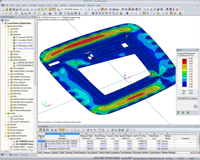
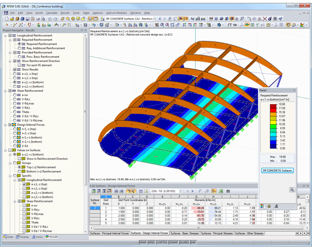
- Fast and clear results output for an immediate overview of the result distribution after the design
- Graphical results output integrated in RFEM; for example, required reinforcement
- Numerical results clearly arranged in tables and graphical display of the results in the model
- Complete integration of results in the RFEM printout report
- Import of results from RSTAB
- Integrated material and cross-section library
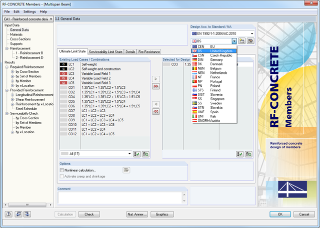
- The module extension EC2 for RSTAB enables design of reinforced concrete according to EN 1992-1-1 (Eurocode 2) and the following National Annexes:
-
DIN EN 1992-1-1/NA/A1:2015-12 (Germany)
-
ÖNORM B 1992-1-1:2018-01 (Austria)
-
Belgium NBN EN 1992-1-1 ANB:2010 for design at normal temperature, and NBN EN 1992-1-2 ANB:2010 for fire resistance design (Belgium)
-
BDS EN 1992-1-1:2005/NA:2011 (Bulgaria)
-
EN 1992-1-1 DK NA:2013 (Denmark)
-
NF EN 1992-1-1/NA:2016-03 (France)
-
SFS EN 1992-1-1/NA:2007-10 (Finland)
-
UNI EN 1992-1-1/NA:2007-07 (Italy)
-
LVS EN 1992-1-1:2005/NA:2014 (Latvia)
-
LST EN 1992-1-1:2005/NA:2011 (Lithuania)
-
MS EN 1992-1-1:2010 (Malaysia)
-
NEN-EN 1992-1-1+C2:2011/NB:2016 (Netherlands)
- NS EN 1992-1 -1:2004-NA:2008 (Norway)
-
PN EN 1992-1-1/NA:2010 (Poland)
-
NP EN 1992-1-1/NA:2010-02 (Portugal)
-
SR EN 1992-1-1:2004/NA:2008 (Romania)
-
SS EN 1992-1-1/NA:2008 (Sweden)
-
SS EN 1992-1-1/NA:2008-06 (Singapore)
-
STN EN 1992-1-1/NA:2008-06 (Slovakia)
-
SIST EN 1992-1-1:2005/A101:2006 (Slovenia)
-
UNE EN 1992-1-1/NA:2013 (Spain)
-
CSN EN 1992-1-1/NA:2016-05 (Czech Republic)
-
BS EN 1992-1-1:2004/NA:2005 (United Kingdom)
-
CPM 1992-1-1:2009 (Belarus)
-
CYS EN 1992-1-1:2004/NA:2009 (Cyprus)
-
- In addition to the National Annexes (NA) listed above, you can also define a specific NA, applying user‑defined limit values and parameters.
- Optional presetting of partial safety factors, reduction factors, neutral axis depth limitation, material properties, and concrete cover
- Determination of longitudinal, shear, and torsional reinforcement
- Design of tapered members
- Cross‑section optimization
- Representation of minimum and compression reinforcement
- Determination of editable reinforcement proposal
- Crack width analysis with optional increase of the required reinforcement in order to keep the defined limit values of the crack width analysis
- Nonlinear calculation with consideration of cracked cross‑sections (for EN 1992‑1‑1:2004 and DIN 1045‑1:2008)
- Considering tension stiffening
- Considering creep and shrinkage
- Deformations in cracked sections (state II)
- Graphical representation of all result diagrams
- Fire resistance design according to the simplified method (zone method) according to EN 1992‑1‑2 for rectangular and circular cross‑sections. Thus, fire resistance design of brackets is possible as well.
- Cross-section modeling using surfaces, openings, and point areas (reinforcements) limited by polygons
- Automatic or individual arrangement of stress points
- Extensible library of concrete, steel, and reinforcing steel materials
- Cross-section properties of reinforced concrete and composite cross-sections
- Stress analysis with yield hypothesis according to von Mises and Tresca
- Reinforced concrete design according to:
-
DIN 1045-1:2008-08
-
DIN 1045:1988-07
-
ÖNORM B 4700: 2001-06-01
-
 EN 1992-1-1:2004
-
- For the design according to EN 1992-1-1:2004, the following National Annexes are available:
-
DIN EN 1992-1-1/NA:2013-04 (Germany)
-
NEN-EN 1992-1-1/NA:2011-11 (Netherlands)
-
CSN EN 1992-1-1/NA:2006-11 (Czech Republic)
-
ÖNORM B 1992-1-1:2011-12 (Austria)
-
UNE EN 1992-1-1/NA:2010-11 (Spain)
-
EN 1992-1-1 DK NA:2007-11 (Denmark)
-
SIST EN 1992-1-1:2005/A101:2006 (Slovenia)
-
NF EN 1992-1-1/NA:2007-03 (France)
-
STN EN 1992-1-1/NA:2008-06 (Slovakia)
-
SFS EN 1992-1-1/NA:2007-10 (Finland)
-
BS EN 1992-1-1:2004 (United Kingdom)
-
SS EN 1992-1-1/NA:2008-06 (Singapore)
-
NP EN 1992-1-1/NA:2010-02 (Portugal)
-
UNI EN 1992-1-1/NA:2007-07 (Italy)
-
SS EN 1992-1-1/NA:2008 (Sweden)
-
PN EN 1992-1-1/NA:2008-04 (Poland)
-
NBN EN 1992-1-1 ANB:2010 (Belgium)
-
NA to CYS EN 1992-1-1:2004/NA:2009 (Cyprus)
-
BDS EN 1992-1-1:2005/NA:2011 (Bulgaria)
-
LST EN 1992-1-1:2005/NA:2011 (Lithuania)
-
SR EN 1992-1-1:2004/NA:2008 (Romania)
-
- In addition to the National Annexes (NA) listed above, you can also define a specific NA, applying user‑defined limit values and parameters.
- Reinforced concrete design for stress-strain distribution, available safety, or direct design
- Results of reinforcement list and total reinforcement area
- Printout report with option to print a short form
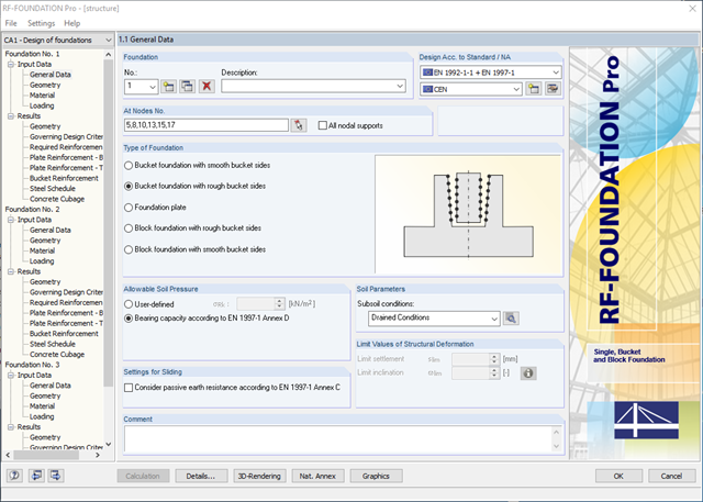
- Available types of foundation:Pure foundation plate (optionally without reinforcement)
- Bucket foundation with smooth bucket sides
- Bucket foundation with rough bucket sides
- Block Foundation with Smooth Bucket Sides
- Block foundation with rough bucket sides
- Design according to EN 1992-1-1 and EN 1997-1
- The following National Annexes of Eurocode 2 and Eurocode 7 are available:
-
DIN EN 1992-1-1/NA/A1:2015-12 | DIN EN 1997-1/NA:2010-12
-
ÖNORM B 1992-1-1:2018-01 | ÖNORM B 1997-1:2007-11
-
DK EN 1992-1-1/NA:2013 | DK EN 1997-1/NA:2007
-
BDS EN 1992-1-1:2005/NA:2011 | BDS EN 1997-1:2005/NA:2012
-
SFS EN 1992-1-1/NA:2007-10 | SFS EN 1997-1/NA:2004-01
-
NF EN 1992-1-1/NA:2016-03 | NF EN 1997-1/NA:2006-09
-
UNI EN 1992-1-1/NA:2007-07 | DIN EN 1997-1/NA:2005-01
-
NEN EN 1992-1-1 C2:2011/NB:2016-11 | NEN EN 1997-1+C1:2012/NB:2012
-
PN EN 1992-1-1/NA:2010 | PN EN 1997-1/NA:2005-05
-
STN EN 1992-1-1/NA:2008-06 | STN EN 1997-1/NA:2005-10
-
SIST EN 1992-1-1:2005/A101:2006 | SIST EN 1997-1/NA:2006-03
-
UNE EN 1992-1-1/NA:2013 | UNE EN 1997-1:2010
-
EN 1992-1-1/NA:2008 | Svensk EN 1997-1:2005/AC:2009
-
CSN EN 1992-1-1/NA:2016-05 | CSN EN 1997-1/NA:2014-06
-
BS EN 1992-1-1:2004/NA:2005 | BS EN 1997-1:2004
-
TKP EN 1992-1-1:2009 | TKP EN 1997-1:2009
-
CYS EN 1992-1-1:2004/NA:2009 | CYS EN 1997‑1/NA:2004
-
In addition to the National Annexes (NA) listed above, you can also define a specific NA, applying user‑defined limit values and parameters.
- Automatic calculation of governing loading from load cases
- Specification of additional support forces
- Determination of the reinforcement proposal for the bottom and top plate reinforcement considering the most favorable combination of mat and rebars
- Individual adjustment of reinforcement proposal
- Results of foundation reinforcement in detailed reinforcement drawings
- Results displayed in tables and graphics
- Visualization of foundation, columns, and reinforcement in 3D rendering
- Determination of longitudinal, shear, and torsional reinforcement
- Representation of minimum and compression reinforcement
- Determination of neutral axis depth, concrete and steel strains
- Design of member sections affected by bending about two axes
- Design of tapered members
- Determination of deformation in state II, for example according to EN 1992-1-1, 7.4.3
- Considering tension stiffening
- Considering creep and shrinkage
- Precise breakdown of reasons for failed design
- Design details of all design locations for better traceability of reinforcement determination
- Options to optimize cross‑sections
- Visualization of concrete section with reinforcement in 3D rendering
- Output of complete steel schedule
- Fire resistance design according to the simplified method (zone method) according to EN 1992‑1‑2 for rectangular and circular cross‑sections
- Optional extension of the RF‑CONCRETE Members add‑on module with a nonlinear calculation of frameworks for the ultimate and serviceability limit states. The extension enables the design of potentially unstable structural components by means of a nonlinear calculation, or a nonlinear deformation analysis of 3D frameworks. Find more information under the product description of the RF-CONCRETE NL add‑on module.
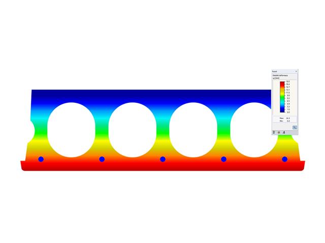
- Deformation analyses of reinforced concrete surfaces without or with cracks (state II) by applying the approximation method (for example, deformation analysis according to EN 1992-1-1, Cl. 7.4.3 )
- Tension stiffening of concrete applied between cracks
- Optional consideration of creep and shrinkage
- Graphical representation of results integrated in RFEM; for example, deformation or sag of a flat slab
- Numerical results clearly arranged in tables and graphical display of the results in the model
- Complete integration of results in the RFEM printout report
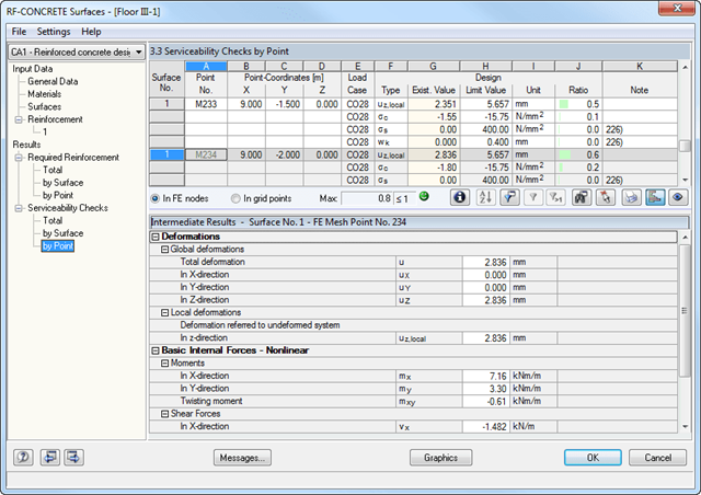
- Iterative nonlinear calculation of deformations for beam and plate structures consisting of reinforced concrete by determining the respective element stiffness subjected to the defined loads
- Deformation analyses of cracked reinforced concrete surfaces (state II)
- General nonlinear stability analysis of compression members made of reinforced concrete; for example, according to EN 1992-1-1, 5.8.6
- Tension stiffening of concrete applied between cracks
- Numerous National Annexes available for the design according to Eurocode 2 (EN 1992-1-1:2004 + A1:2014, see EC2 for RFEM)
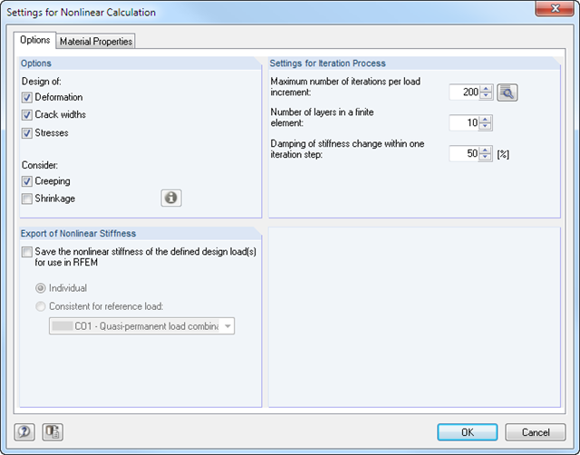
- Optional consideration of long-term influences such as creep or shrinkage
- Nonlinear calculation of stresses in reinforcing steel and concrete
- Nonlinear calculation of crack widths
- Flexibility due to detailed setting options for basis and extent of calculations
- Graphical representation of results integrated in RFEM; for example, deformation or sag of a flat slab made of reinforced concrete
- Numerical results clearly arranged in tables and graphical display of the results in the model
- Complete integration of results in the RFEM printout report